Body electrics: the 10S bus, the battery bay, the power skid and the CAN buses
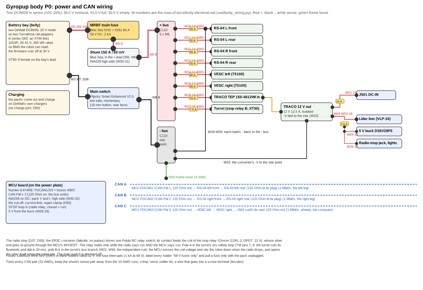
The P0 power system of Gyropup's body as built from cad/body_wiring.py (the wire list and the drawing),
cad/body_battery.py (the battery bay), cad/body_layout.py (where every part sits on the power plate) and
exports/body/bom.json (what to buy, by catalogue key). It is the build package for milestone M5's power skid: a
person with the parts and a crimper can build and test it from this page and
the wiring diagram. Decisions: D65 (the two DeWalt packs, the 10S bus; it replaces D43
and D54), D55 (the protection and the switch), D60 (the fuse board, P3), D66 (the turret's own branch). Rewritten
2026-10-27 for D65.

1. The numbers
| Packs | two DeWalt DCB609 FLEXVOLT 9.0 Ah in 20 V mode (5S3P each), in series on two Terrafirma rail adapters: 10S3P |
| Voltage | 36 V nominal; about 41 V full (4.1 V a cell); empty at 30.0 V (3.0 V a cell: the firmware's latched cut-off) |
| Capacity | 9.0 Ah, 360 Wh rated (DeWalt's 180 Wh a pack) |
| Current | 80 A for at most 0.5 s (a jump's push draws about 70 A for 0.3 s), 30 A continuous: the adapters' stated rating, enforced by the firmware |
| Pack protection | none the robot can read: the firmware's windows (docs/body-firmware.md 5) and the MRBF |
| Main fuse | MRBF 80 A (Blue Sea 5181 on a 5191 block), 58 V DC, 2 kA interrupting at 58 V |
| Branch fuses | Littelfuse MINI 58V (0997 series), 1 kA at 58 V |
| Rails | 12 V 12.5 A isolated (TRACO TEP 150-4812WI, 18-75 V in): the J501 and the 12 V loads; 5 V 3.2 A (Pololu D36V28F5 from the 12 V) |
| Below SELV | 41 V is under the 60 V DC limit: nothing on the robot is a shock hazard, but the packs' short-circuit current is |
Every load is rated across 30-41 V (D65): the RS-04 24-60 V, the 75100 14-84 V, the switch 12-84 V, the TRACO 18-75 V, the MINI 58V fuses and the MRBF 58 V. Regeneration is clamped over 41.5 V and the robot latches off over 44.0 V (the firmware), far under the RS-04's 60 V fault.
2. The battery
2.1 The bay
cad/body_battery.py; docs/body-sections.md 1 for why the belly. The two packs hang from their rail adapters as from
a tool, rails along x, in a bay under the belly plate between the knees (318 x 102 x 132 mm; the robot sits on its TPU
skids under a 139 mm leg). The front pack slides out of the front door, the rear one out of the rear door; each door is
held by two knurled M3 thumbscrews (no tool). The adapters' leads meet in the 30 mm between the packs:
- Each adapter screws to its printed plate (M3 into heat-set inserts set from the adapter's own holes: their pattern is not published), the plate up into the belly's S-M4-0 nuts (four M4 x 12).
- Check each pack's mode: the FLEXVOLT slider must stay out (20 V mode): 18-20.5 V on its adapter's leads.
- The series link (W2): the front adapter's - to the rear adapter's + through an XT90-S pair; unplugged, each half of the bay is 18-20 V and the bay's lead is dead.
- The bay's lead (W1, W3): the front adapter's + and the rear adapter's - to the bay's XT90-S female; up through the belly's slot at x -30 into the spine's gap, forward to the tray's slot and up to the plate.
2.2 Charging
The packs come out and charge on DeWalt's own chargers (the user's): the robot has no charge port and no dock contacts (D64's dock is overtaken). Unplug the series link before a pack comes out.
3. The main path and the branches
On the power plate (exports/body/sendcutsend/power_plate_*.dxf; the layout in cad/body_layout.py): the bay's +
lead goes to the MRBF block's battery stud (its M8 post sits in a printed PETG insulating bushing in the plate, the
block on 3 mm PETG spacers), the 80 A fuse to the shunt in the + lead, then the + bus bar; the bay's - lead goes to
the main switch (Flipsky Smart Enhanced V2.0, momentary mode: hold 0.3 s on, 1 s off; its smart mode off), then the
- bus bar. The shunt is on the + side on purpose (issue #11, docs/body-fuse-board.md 1): the INA228's inputs may not go more than 0.3 V below its ground (the MCU's, the switched - bus). With the shunt in the - lead ahead of the low-side switch, opening the switch lets the - bus float up toward + while the INA228's inputs stay at the pack's -: the chip dies and its input clamps carry the load round the open switch. High side, its inputs sit 30-41 V above its ground whether the switch is on or off, inside its 85 V common mode. Flipsky draws its switch on the negative: read the wiring card that comes with it before the first wire; if it is high side, the switch moves into the + lead after the shunt. The bus bars are SendCutSend C110 copper (0.125 in, cut only, five Ø6.4 holes each) on printed insulators: each lug stack is an M6 x 16 socket head down through the lug(s) and the bar into a DIN 985 nyloc nut held in a hex pocket of the insulator, its tip 1.5 mm above the insulator's floor, so no screw of a bar reaches the plate. (SendCutSend does no service, tapping included, on a part under 1 in wide: its app refused the 20 mm bar's taps when the prices were read, 2026-10-27; three threads of copper were a poor hold for a lug anyway.) A tap with no lug gets no screw.
Every branch has its own MINI 58V fuse in an inline holder on the + side, as close to the bus bar as the lead allows. The holders are rated 32 V by Eaton; the fuse does the interrupting (1 kA at 58 V), so each holder is labelled 58 V fuses only and a fuse is pulled only with the pack unplugged (D55). A fuse board with PCB holders (Keystone 3568, JLCPCB) replaces them in P3.
3.1 The wire list
Red +, black -, white sense or signal, green the frame bond. Silicone wire throughout (BNTECHGO, 200 °C, 600 V). Lengths
are cut to the plate in P0 and recorded. Every live end on the body is a socket (D58, hazard 11): the bus branch
leads end in XT60H-F (the turret's in XT30U-F) and the 12 V ones in XT30U-F; the devices' leads carry the pins (the RS-04 pigtails'
XT60H-M are the leg's, the VESC leads', the J501's and the lidar box's adapter leads' are in this order). The table is
written by cad/body_wiring.py from its wire list; cad/test_body.py checks that no body-side lead ends in a pin.
| Wire | From | To | AWG | Colour | Ends | Fuse | Why |
|---|---|---|---|---|---|---|---|
| W1 | front adapter + (its 10 AWG lead) | XT90-S female (the bay's lead) + | 10 | red | XT90-S solder cup | - | the adapter's own lead (Terrafirma, 10 AWG, 30 A stated): on the pack's side of the MRBF, unfused as every pack lead; keep it to its 300 mm |
| W2 | front adapter - | rear adapter + (the series link) | 10 | black | XT90-S pair (in the bay's middle) | - | the two packs in series: the link unplugs so each half is 18 V when the bay is serviced |
| W3 | rear adapter - | XT90-S female (the bay's lead) - | 10 | black | XT90-S solder cup | - | the pair's negative |
| W4 | XT90-S male (robot) + | MRBF block, battery stud (M8) | 8 | red | lug M8 | - | unfused until the MRBF: keep it short (<150 mm) |
| W5 | MRBF block, load stud (M8) | shunt, battery side (M8) | 8 | red | lugs M8 | MRBF 80 A | the shunt on the + side: the INA228 reads it high side (docs/body-fuse-board.md 1); its base insulates it from the plate |
| W6 | shunt, load side (M8) | + bus bar, tap 1 (M6) | 8 | red | lugs M8 / M6 | MRBF 80 A | the whole robot |
| W7 | XT90-S male (robot) - | main switch IN- (B-) | 8 | black | ferrule / its lead | - | Flipsky draws the switch on the negative: check its card |
| W8 | main switch OUT- (P-) | - bus bar, tap 1 (M6) | 8 | black | lug M6 | - | the switched negative: everything below is off with it |
| W10 | + bus tap 2 | RS-04 left front (XT60H) | 14 | red | lug M6 / XT60H-F | MINI 58V 20 A | ~12 A at a jump, 25 A peaks: 14 AWG silicone; the motor's 450 mm pigtail carries the XT60H-M |
| W11 | + bus tap 2 | RS-04 left rear (XT60H) | 14 | red | lug M6 / XT60H-F | MINI 58V 20 A | as W10 (two lugs share the tap) |
| W12 | + bus tap 3 | RS-04 right front (XT60H) | 14 | red | lug M6 / XT60H-F | MINI 58V 20 A | as W10 |
| W13 | + bus tap 3 | RS-04 right rear (XT60H) | 14 | red | lug M6 / XT60H-F | MINI 58V 20 A | as W10 |
| W14 | + bus tap 4 | VESC left (Flipsky 75100) + | 12 | red | lug M6 / XT60H-F | MINI 58V 30 A | the wheel: its battery current limit 20 A in VESC Tool (the fuse board's FL1 holders carry 22 A); its own lead carries the XT60H-M |
| W15 | + bus tap 4 | VESC right + | 12 | red | lug M6 / XT60H-F | MINI 58V 30 A | as W14 |
| W16 | + bus tap 5 | TRACO TEP 150-4812WI Vin+ | 18 | red | lug M6 / ferrule | MINI 58V 10 A | 150 W out: 5.6 A in at 30 V |
| W22 | + bus tap 5 | stop relay, pole B (in): the turret's branch | 16 | red | lug M6 / screw terminal | MINI 58V 7.5 A | D66: the turret's own robot on the bus (its Orin NX ~40 W, flywheel bursts to ~140 W: 4.7 A at 30 V); 7.5 A keeps the G2RL-2's contact under its 8 A (about 6 A breaking at 41 V: docs/body-fuse-board.md); the stop relay cuts it |
| W18 | - bus taps 2-3 | RS-04 x 4 (XT60H) | 14 | black | lug M6 / XT60H-F | - | returns, one per motor (the - of W10-W13's plugs) |
| W19 | - bus tap 4 | VESC left, right - | 12 | black | lug M6 / XT60H-F | - | returns (the - of W14-W15's plugs) |
| W20 | - bus tap 5 | TRACO Vin-, the turret's XT30U-F - | 16 | black | lug M6 / ferrule / XT30 | - | returns |
| W21 | TRACO +V | J501 DC-IN (XT30) | 16 | red | ferrule / XT30U-F | MINI 10 A (inline) | the J501 at 12 V (12-36 V in): 60 W peak, 5 A; its DC-IN adapter lead carries the XT30U-M |
| W43 | TRACO +V | 12 V loads: lidar box, buck, jack, lights, eyes | 16 | red | ferrule / Wago 221 | MINI 58V 7.5 A (inline) | about 40 W: the VLP-16 8 W (3 A at spin-up), the SSC1 pods, the eyes, the 5 V buck |
| W23 | TRACO -V | J501 return; star point | 16 | black | ferrule / XT30U-F | - | one tie from -V to the - bus (the CAN reference) |
| W24 | 12 V loads (W43) | lidar interface box (XT30) | 18 | red | Wago 221 / XT30U-F | (W43's 7.5 A) | the box's lead carries the XT30U-M |
| W25 | 12 V loads (W43) | 5 V buck VIN (Pololu D36V28F5) | 22 | red | Wago 221 / solder | (W43's 7.5 A) | ~0.6 A at 12 V |
| W26 | 12 V loads (W43) | radio-stop jack pin 3 (+12 V) | 22 | red | Wago 221 / jack | (W43's 7.5 A) | D37: the jack offers 12 V |
| W27 | TRACO -V | lidar box, buck, jack GND | 18 | black | ferrule | - | the 12 V loads' returns |
| W28 | 5 V buck VOUT | Nucleo E5V, 3 CAN Pal, VN-100, radio receiver | 22 | red | solder / GH | (the buck's 3.2 A limit) | ~1 A in all |
| W29 | 5 V buck GND | the same, GND | 22 | black | solder / GH | - | |
| W30 | shunt sense + (battery side screw) | INA228 IN+ | 22 | white | ring / screw terminal | - | Kelvin pair, twisted, away from the 8 AWG; high side: 30-41 V above the INA228's ground, inside its 85 V |
| W31 | shunt sense - (load side screw) | INA228 IN- | 22 | white | ring / screw terminal | - | the INA228's own 15 mOhm shunt is removed |
| W32 | + bus tap 5 | INA228 VBUS | 22 | red | lug M6 / ring | MINI 58V 5 A (its own inline holder) | pack voltage, 85 V input; 22 AWG carries 7 A |
| W33 | frame (a tray PEM stud) | - bus star point | 14 | green | ring M5 / lug M6 | - | a + short to the frame blows a fuse, not leaves it live; 14 AWG: a + lead chafed ahead of its branch fuse puts the MRBF's let-through on it |
| W34 | stop relay, pole B (out) | the turret's XT30U-F + | 16 | red | screw terminal / XT30U-F | MINI 58V 7.5 A (W22) | dead whenever the stop relay is open; the turret's lead carries the XT30U-M |
| W36 | J501 Ethernet (its second port or a switch) | the turret's RJ45 | None | blue | Cat 6, 0.5 m | - | D66: the turret's link (it had can1) |
| W37 | stop relay, pole A (closed = run) | the turret's safety loop (SAFETY_A, SAFETY_B) | 22 | white | twisted pair | - | the turret's dry safety loop (12 V at 2 mA; D41 D7: it cuts the flywheels and the dial in hardware) |
| W38 | stop relay coil, + side | MCU STOP sense (divider 12 V to 3.3 V) | 22 | white | GH | - | 12 V on the coil = the radio says run: the MCU sits the robot down when it drops (D37) |
| W39 | 12 V loads (W43) via the RC switch's contact | stop relay coil, + side | 22 | red | solder / screw terminal | (W43's 7.5 A) | the coil (12 V, 33 mA) is fed only while the radio says run; its - side through the MCU's MOSFET (MCU_RUN), a diode across it |
| W50 | VESC left phases A/B/C | left wheel phases (its lead's DTP04-4P) | 14 | yellow/green/blue | DTP06-4S plug + WM-4S wedge, 3 x 0462-203-12141 sockets (4th cavity plugged, 114017) | - | D69: 30 A motor peak for 0.5 s, 10 A continuous; 14 AWG silicone, 400 mm to the cheek's gland; no fuse (the VESC limits it) |
| W51 | VESC left halls (5 V, GND, H1-H3) + motor NTC | left wheel sensors (its lead's DT04-6P) | 20 | per VESC | DT06-6S plug + W6S wedge, 6 x 0462-201-20141 sockets | - | D69: halls and the stator NTC; a shielded 6-core, shield to the VESC's GND only |
| W52 | VESC right phases A/B/C | right wheel phases (its lead's DTP04-4P) | 14 | yellow/green/blue | DTP06-4S plug + WM-4S wedge, 3 x 0462-203-12141 sockets (4th cavity plugged, 114017) | - | as W50 |
| W53 | VESC right halls (5 V, GND, H1-H3) + motor NTC | right wheel sensors (its lead's DT04-6P) | 20 | per VESC | DT06-6S plug + W6S wedge, 6 x 0462-201-20141 sockets | - | as W51 |
3.2 The rails
- 12 V (TRACO TEP 150-4812WI, 150 W, 18-75 V in, isolated): the J501 (12-36 V in; 60 W at MAXN, W21 on 10 A) and the 12 V loads (W43 on 7.5 A): the lidar interface box (8 W, 3 A at spin-up), the 5 V buck (~5 W), the radio-stop jack; in P3 the SSC1 pods (25.6 W) and the eyes, switched on after the lidar has spun up. About 100 W at the most: two thirds of its rating. It replaces the DDR-120C-24 (which starts at 33.6 V, inside the 10S range) and the DDR-60L-12 (D65).
- The turret (D66) is not on a rail: its own robot takes 30-41 V from the bus on a 7.5 A branch (W22) through the stop relay's pole B (W34) and makes its own rails.
- 5 V (Pololu D36V28F5 from the 12 V, 3.2 A): the Nucleo (E5V), three CAN Pal, the VN-100, the radio receiver; about 1 A in all.
The converter is isolated; its -V is tied once to the - bus at the star point (W23), so the MCU, the CAN transceivers, the J501 and the motor drivers share one reference. The frame is bonded to the star point (W33, 14 AWG): a + lead chafed through to the aluminium blows its fuse instead of leaving the frame live.
4. CAN
| Bus | Master | Nodes, in order | Notes |
|---|---|---|---|
| A | MCU FDCAN1 (CAN Pal 1, 120 Ohm on) | RS-04 left front → RS-04 left rear (120 Ohm at its plug) | 1 Mbit/s, the left leg |
| B | MCU FDCAN2 (CAN Pal 2, 120 Ohm on) | RS-04 right front → RS-04 right rear (120 Ohm at its plug) | 1 Mbit/s, the right leg |
| C | MCU FDCAN3 (CAN Pal 3, 120 Ohm on) | VESC left → VESC right → J501 can0 (its own 120 Ohm on) | 1 Mbit/s: wheels, the computer |
The turret (D66) talks to the J501 over Ethernet, not CAN.
All 1 Mbit/s classic CAN (the RS-04s and the VESCs speak it; the G474's FDCAN runs it), 22 AWG twisted by hand at
about 30 twists a metre, 120 Ohm at both ends of each bus and nowhere else (the CAN Pal's switch, the J501's built-in
terminator). The J501's two ports are capacitively isolated (Seeed wiki, read 2026-10-27); if only one comes up on the
board (ip link), bus C moves to an isolated USB-CAN adapter.
5. The radio stop and the switches
The radio stop (D37, D55): the ER3C-i receiver (failsafe: no pulses) drives one Pololu RC relay switch; its contact feeds the coil of the stop relay (Omron G2RL-2, DPDT, 12 V), whose other end goes to ground through the MCU's MOSFET. The relay holds only while the radio says run AND the MCU says run. Pole A is the turret's dry safety loop (TM pins 7, 8: the turret cuts its flywheels and dial in 20 ms), pole B is in the turret's bus branch (W22, W34: the independent cut); the MCU senses the coil voltage and sits the robot down when the radio drops, and opens the relay itself when the robot sits. The main switch is the hard off.
No contactor, no e-stop button on the robot (D37): the radio stop sits the robot down, and the main switch on the belly is the hard off for a person standing at the robot. The stop relay, its MOSFET (a logic-level N-channel on MCU_RUN), the flyback diode and the 12 V-to-3.3 V divider for the sense sit on the MCU carrier's protoboard. The turret (D66) plugs in with its XT30 (power through pole B), its RJ45 to the J501 and its safety loop on pole A: plug it only with the stop relay open (its input capacitors charge through the plug otherwise; B15 measures the inrush on the 7.5 A fuse and the G2RL-2's contact).
6. Bring-up (P0, on the bench, before the plate goes into the robot)
The whole power skid is one plate: it is built and tested on the bench with dummy loads, then dropped into the body on its four posts. The packs are two DeWalt DCB609 in 20 V mode, in series (D65): the robot is their only protection, so the firmware's cut-off and current limit (docs/body-firmware.md 5) are tested here before any motor runs.
- Continuity, unpowered: every W-row end to end; no + to - or + to plate (> 1 MOhm); the frame bond to the - bus (< 0.1 Ohm, W33 14 AWG). Fuses out. The bus-bar insulators: > 10 MOhm at 50 V from every lug screw to the plate (they are PETG: a carbon-filled print conducts).
- Packs alone: each DCB609 18-20.5 V on its adapter's leads (the FLEXVOLT slider must stay out: 20 V mode); the pair 36-41 V at the bay's XT90 with the series link plugged, 0 V across the link's open XT90 with it unplugged.
- Plug in, switch off: the bus reads 0 V (the low-side switch is open).
- Before the INA228 is wired: the shunt is in the + lead (W5 MRBF load stud to the shunt, W6 the shunt to the
- bus), the switch in the - lead (W7, W8), and nothing of the INA228 is connected to the - lead. If the plate was wired from the 13S drawing (the shunt in the - lead), move the shunt first, or leave the INA228's VIN+ and VIN- unconnected until it is moved: switching off would destroy the INA228 and bypass the switch through its sense lead.
- Switch on (hold the button 0.3 s): the bus at pack voltage. Fit the converter's fuse only: the 12 V and 5 V rails within 2 % of nominal; the 12 V -V to the - bus 0 V.
- MCU: the INA228 reads the pack within 0.2 V of a meter and the current within 0.1 A at a 2 A dummy load on the 12 V rail (high side: discharge reads negative); switching the main switch off and on with the INA228 wired leaves it reading (the check of step 4); with the transmitter switched off the stop relay opens within 0.5 s (the receiver's failsafe), the turret's safety loop reads open and its XT30 dead, and the MCU logs the stop; MCU_RUN low opens it too.
- The firmware's windows on a bench supply in place of the packs (current-limited, 30-45 V): warn at 35.0 V, no jump under 34.0, sit at 32.0, the latched cut-off at 30.0 V under load, the over-charge latch at 44.0 V, no arming over 42.0 V (docs/body-firmware.md 5).
- Branches: fit the RS-04 and VESC fuses one at a time with nothing plugged; then each motor on its own (the leg workstream's bring-up) at a 10 A current limit. The VESCs' battery current limit set to 20 A in VESC Tool (the fuse board's FL1 holders carry 22 A).
- Switch off with the buses loaded: no spark at the XT90 (the switch takes it); the rails fall in order.
- An 80 A, 0.3 s pulse (the two RS-04s stalled at a current limit, or an electronic load) on a fresh pair: the 12 V rail stays up (the TRACO runs down to 18 V), the adapters' contacts under 60 C after ten pulses (B12).
7. Open items
- The Flipsky switch's side (low or high) from its wiring card on arrival (section 3).
- The packs' prospective short-circuit current: DeWalt publishes none; two DCB609 in series can source more than the MINI 58V's 1 kA into a dead short, and nothing in the packs limits it. The MRBF (2 kA) is the last line: keep every unfused lead (W1-W4) short and sleeved.
- The adapters' outline and mounting holes (Terrafirma publishes no drawing): measure one, then set the inserts in the printed adapter plates; and that the adapter leaves the FLEXVOLT slider out (20 V mode).
- The TRACO's height (35.7 mm per its outline; Digi-Key lists one variant at 40.6) and its base flange's slots.
- The FL1 fuse holders' DC rating and whether a standard 32 V MINI fuse seats in them (docs/body-fuse-board.md 10).
- The INA228 breakout's on-board shunt removed (a 15 mOhm resistor in parallel with the 0.33 mOhm external shunt would take 2 % of the current: small, but it is not rated for it).